Wednesday, November 2, 2022

Exploring the security configuration of AMD platforms

by Enrique Nissim, Krzysztof Okupski and Joseph Tartaro


TLDR: We present a new tool for evaluating the security of AMD-based platforms and rediscover a long-forgotten vulnerability class that allowed us to fully compromise SMM in the Acer Swift 3 laptop (see Acer's advisory).


Introduction

In the last decade, a lot of interesting research has been published around UEFI and System Management Mode (SMM) security. To provide a bit of background, SMM is the most privileged CPU mode on x86-based systems; it is sometimes referred to as ring -2 as it is more privileged than the kernel and even the hypervisor. Therefore, keeping SMM secure must be one of the main goals of the UEFI firmware.

One thing that caught our attention is that most, if not all, of the publicly available material is focused on Intel-based platforms. Since the release of CHIPSEC [1], the world has had a tool to quickly determine if the firmware does a good job protecting the system after the DXE phase and, as a result, it is hard to find misconfigured firmware in laptops from any of the major OEMs in 2022.

Make no mistake, it is not that AMD-based platforms are free from bugs [2]. Nevertheless, judging by their description, these seem to be associated with SMI handlers rather than platform security configurations. In contrast, the only presentation we found mentioning AMD platform security was done by Pete Markowsky in 2015 [3].

This blog walks through the discovery and exploitation of a security issue that was automatically identified by an in-house developed tool.


The Tool

Platbox is a firmware assessment tool that allows you to retrieve chipset configuration values and interact with PCIe devices, physical memory, MSRs, and so on. The project was born back in 2018 as part of a security evaluation for an OEM's Intel-based platform; however, we recently extended it to support AMD systems.


Source code, compiled binaries, and examples can be found here: https://github.com/IOActive/Platbox

Next, we evaluate the security of one of our targets AMD systems and demonstrate how it can be used to find chipset configuration issues.


The Test-Run


In order to put our tool to the test, we ran it against the Acer Swift 3 (model no. SF314-42; BIOS v1.10), the output of which is shown below:

PS C:\Users\IOActive\Desktop\Platbox\PlatboxClient> .\build\build64\Release\platbox_cli.exe cli
>>> chipset

MemoryRange: fe000000

RomProtect_0 
- Base: ff73a000
- RangeUnit: 1
- Range: 00000039
- Protected size: 00390000
- WriteProtected: 1
- ReadProtected: 0
- Total range [ff73a000, ffad9fff)
RomProtect_1
- Base: fff20000
- RangeUnit: 0
- Range: 000000df
- Protected size: 000df000
- WriteProtected: 1
- ReadProtected: 0
- Total range [fff20000, ffffffff)
RomProtect_2
- Base: 00000000
- RangeUnit: 0
- Range: 00000000
- Protected size: 00000000
- WriteProtected: 0
- ReadProtected: 0
- Total range [00000000, 00000fff)
RomProtect_3
- Base: 00000000
- RangeUnit: 0
- Range: 00000000
- Protected size: 00000000
- WriteProtected: 0
- ReadProtected: 0
- Total range [00000000, 00000fff)

SPI BASE: fec10000

SPIx1D - SpiProtectEn0: 1
SPIx1D - SpiProtectEn1: 1
SPIx1D - SpiProtectLock: 1

LPC ROM Address Range1 Start: 0
LPC ROM Address Range1   End: fffff
LPC ROM Address Range2 Start: ff000000
LPC ROM Address Range2   End: ffffffff

-> MSR:[c0010111]: 00000000AEF43000
MSR C001_0111 SMM Base Address (SMM_BASE)
 => Base: aef43000
   -> SMI-Handler Entry Point: aef4b000
   -> SMM Save-State Area    : aef52e00

-> MSR:[c0010112]: 00000000AE000000
MSR C001_0112 SMM TSeg Base Address (SMMAddr)
 => Value: ae000000

-> MSR:[c0010113]: 0000FFFFFF006603
MSR C001_0113 SMM TSeg Mask (SMMMask)
 => Value: ff006603
   -> TSegMask: ff000000
   -> TMTypeDram: 6
   -> AMTypeDram: 6
   -> TMTypeIoWc: 0
   -> AMTypeIoWc: 0
   -> TClose: 0
   -> AClose: 0
   -> TValid: 1
   -> AValid: 1

-> MSR:[c0010015]: 0000000109000010
MSR C001_0015 Hardware Configuration (HWCR)
 => Value: 9000010
   -> SMMLock: 0

[...]

    As we can see, the tool has extracted a variety of information from the system, namely:
    • Flash protected ranges
    • Flash lock configuration
    • TSEG memory range
    • SMM base address
    • SMM lock configuration

          The first part describes the protections applied to the flash that prevent any run-time access (including from SMM). Each protected range defines (i) a memory range in flash and (ii) read/write access permissions. These protections are applied at boot-time and should be locked to prevent tampering.
              The second part describes protections applied to the SMM memory that prevent any run-time access from the OS. To this end, the so called TSEG region is used; the configurations include, among others, (i) the TSEG memory range and (ii) whether it is active or not. As before, these protections are applied at boot-time and should be locked to prevent modification.
                Note that for the sake of brevity the remainder of the output has been truncated. 


                The Vulnerability

                We see that the tool has found that the SMM lock configuration bit in the HWCR is set to 0. Let's try to understand why this is an issue.

                According to AMD specifications [4], the SMM lock configuration bit in the HWCR is used to indicate that (i) SMM code is running in either the so called ASEG or TSEG region and (ii) that certain SMM registers are read-only:


                The reference to another section at the end of the definition provides further clarification: it states that specifically MSRC001_0112 and MSRC001_0113 registers are configured to be read-only when the SMM lock bit is set:


                Digging deeper into the aforementioned registers, we see that the MSRC001_0112 register corresponds to the TSEG base address. This is the base address of a protected memory region that can only be accessed when the CPU is in SMM.


                The MSRC001_0113 register, on the other hand, is the TSEG mask that configures, among others, the size of the protected TSEG region, the memory range type and whether the TSEG or ASEG region should be enabled.


                However, the definition of this register also tells us an important fact, namely that the ASEG and TSEG region are used to securely store SMM code and data so that it cannot be accessed when the CPU is not in SMM. If we can disable these regions, we can directly access SMM memory from the kernel.

                The bits controlling whether the ASEG and TSEG regions are enabled are bit 0 and bit 1 in the SMM mask register, respectively. By setting these bits to 0, the protections should be disabled.


                Having found this issue in a relatively modern system came as quite a surprise, as  it was first documented by Duflot et. al. in 2006 [5] and since then, at least for Intel platforms, OEMs have basically eradicated it.


                Exploitation

                To exploit this vulnerability, we run the Read&Write Utility and add the SMM TSEG mask register to the list of custom MSR registers:


                Next, we set the last two bits, corresponding to the ASEG and TSEG valid bits, on all CPUs to 0:


                Finally, we confirm that the beginning of the TSEG region is accessible by inspecting the memory:


                The magic SMMS3_64 at the start of the TSEG is the first member of the SMM_S3_RESUME_STATE structure, which, based on the EDKII reference code, gets mapped here (https://github.com/tianocore/edk2/blob/7c0ad2c33810ead45b7919f8f8d0e282dae52e71/OvmfPkg/SmmAccess/SmramInternal.c#L187):


                From here on exploitation is trivial as we have full read and write access to SMM memory. 

                Here is the SMRAM dump for those who want to perform additional analysis on it: https://github.com/IOActive/uefi_research/tree/main/acer_swift_3_sf314_42


                Timeline

                • 06 August 2022: Reported vulnerability
                • 22 September 2022: Confirmed vulnerability and working on fix
                • 14 October 2022: Discussing timelines
                • 18 October 2022: Confirmed patch release date
                • 20 October 2022: Patch released
                • 24 October 2022: Acer published bulletin

                References


                [3] Ring -1 vs Ring -2: Containerizing Malicious SMM Interrupt Handlers on AMD-V, Pete Markowsky

                [4] BIOS and Kernel Developer's Guide (BKDG) for AMD Family 15h Models 70h-7Fh Processors, Revision 3.09, AMD

                [5] Using CPU System Management Mode to Circumvent Operating System Security Functions, Duflot et al

                Thursday, September 29, 2022

                NFC RELAY ATTACK ON TESLA MODEL Y 

                 
                Josep Pi Rodriguez, Principal Security Consultant, walks you through the proof-of-concept and technical details of exploitation for IOActive’s recent NFC relay attack research on the newest Tesla vehicle, the Model Y. To successfully carry out the attack, IOActive reverse-engineered the NFC protocol Tesla uses between the NFC card and the vehicle, and we then created custom firmware modifications that allowed a Proxmark RDV4.0 device to relay NFC communications over Bluetooth/Wi -Fi using the Proxmark’s BlueShark module. 

                It’s well-known in the vehicle security industry that NFC relay attacks (as well as Radio Frequency relay attacks) are a serious issue, and that they’re currently being used to steal cars. This type of attack consists of relaying cryptographic material between the vehicle and the virtual key (NFC card or smartphone).

                Here you can find the paper with full technical details:


                Also, there are 2 videos where you can see the attack in realtime:

                Attack in testing environment with logs. 

                The Proxmark device is connected to a laptop with USB cable to show the Proxmark’s logs in realtime on the laptop’s screen. The Tesla NFC card is placed on an USB NFC reader that is connected to another laptop to show the logs of the python tool created during the initial phases of testing. This second laptop with the python tool will act as the smartphone that the mule will use in the real attack.


                Attack using Proxmark and smartphone on the streets.

                In the second video, we demonstrate the attack in a more real-world scenario using the Proxmark and the smartphone application. The first attacker waits for the victim to leave the car, then gets close to the vehicle’s reader with the Proxmark. In the meantime, the second attacker will get closer to the victim and use a smartphone to read the Tesla NFC card in the victim’s pocket.


                About final thoughts:

                Time limitation seems to be very permissive, and it was possible to perform this attack via Bluetooth from several meters away, as well as via Wi-Fi with much greater distances. We believe it may be possible to make it work via the Internet as well.

                Only one challenge/response is required to open and drive the car when the “PIN to Drive” feature is not enabled in the vehicle.

                One of the attackers does have to be very close to the victim’s card when the mule is using a smartphone. This distance might change depending on multiple factors, but a distance of 4 cm or less might be fairly precise when using a smartphone. Using a more specialised, high power device might make this distance much bigger. In the following links is possible to read an old paper demonstrating it and also a a link with one of those long range readers that can be hidden in a backpack/purse while performing the attack:


                We actually bought this long range antenna and perform some tests to show that more than 10cm can be used to read the victim's card / smartphone. We will use it in future proof of concepts shortly. The following video shows it working while reading an NFC card with more than 10cm distance:


                However, 4cm can be enough in some scenarios when the victim is distracted, like a crowded night club/disco. If the attacker at the vehicle is ready at the driver’s door, then contact with the victim’s NFC card needs to only be for one to two seconds to be effective.

                It is also important to clarify that this attack also works against smartphones that have the NFC capability to open the vehicle. Instead of targeting the Tesla NFC card, the victim's smartphone would be the target.


                Tuesday, April 5, 2022

                Satellite (In)security: Vulnerability Analysis of Wideye SATCOM Terminals

                By Ethan Shackelford

                Introduction

                This blog post introduces our most recent whitepaper detailing original research into two SATCOM terminals manufactured by Addvalue Technologies, Ltd.: the Wideye iSavi and Wideye SABRE Ranger 5000.

                We identified numerous serious security vulnerabilities in both devices, including broken or backdoored authentication mechanisms, rudimentary data parsing errors allowing for complete device compromise over the network, completely inadequate firmware security, and sensitive information disclosure, including the leaking of terminal GPS coordinates. These issues were present in all reviewed firmware versions, including the currently available release.

                Research Goals

                The primary goal of this research was to determine the security posture of these two SATCOM terminals, whose application spans multiple industries. By taking the results of this research in isolation, IOActive hopes to gain insight into the current state of security in the SATCOM industry. Additionally, by comparing the research results with the conclusions drawn from the research we conducted in 2014 and 2018, it is possible to assess how much progress toward improved security has been made in that time.

                Furthermore, given the bleak outlook of the findings of this research, IOActive hopes that the publication of this information will increase awareness of these issues and make the necessity of immediate corrective action very clear.

                Research Targets

                Wideye iSavi Portable SATCOM Terminal

                The Wideye iSavi is a portable satellite terminal operating over the Inmarsat iSatHub and BGAN services, offering voice, text, and Internet connectivity to devices connecting to the iSavi via a built-in WiFi access point. It is designed for general consumer use as per the Wideye documentation, allowing maintained connectivity for those outside the range of coverage of traditional ground-based Internet infrastructure. It may or may not be configured to be accessible over the broader Internet and can be managed remotely via a web interface or other means.

                Wideye SABRE Ranger 5000

                The Wideye SABRE Ranger 5000, built on technology similar to the iSavi, is a BGAN Machine-to-Machine (M2M) satellite terminal. It is designed to operate and stay connected to the Internet without interruption and is commonly configured for accessibility over the wider Internet, to allow for remote management. It is intended for industrial use, with the Wideye brochure [1] suggesting its use in the following industries:


                Firmware Images

                Despite the varied uses, investigation into the two devices indicated that very similar firmware runs on each. As such, all vulnerabilities identified during this research effect both the iSavi and the Ranger, with the impact varying somewhat for each vulnerability based on the use-case of each device.

                Firmware versions analyzed during this research include:

                iSavi

                • R01.0.0: The version which was pre-installed on the iSavi originally purchased for the research in 2019
                • R01.0.1 and R02.0.0: Firmware versions available for download from the vendor website [2] over the course of research beginning in 2019
                • R02.0.2: Current firmware version available for download from the vendor website as of the publication of this blog post

                SABRE Ranger 5000

                • R01.0.0: The version which was pre-installed on the iSavi originally purchased for the research in 2019
                • R01.0.3: Current firmware version available for download from the vendor website as of the publication of this blog post


                Cyberattacks on SATCOM Infrastructure: Understanding the Threat

                Before elaborating on the vulnerabilities discovered during this research, it is important to understand what kind of threat is posed by any given attack, and how to think about that attack’s impact.

                Attack Vectors

                Since we will be looking at SATCOM terminals, it is important to understand the paths available to an attacker for potential device access. Figure 2 comes from the SABRE Ranger M2M (an older SABRE Ranger model) marketing brochure [3] and lays out the architecture of SATCOM terminal communication nicely. The layout for the iSavi differs slightly, in that its internal network is established over WiFi, but the diagram is still accurate at a high level.


                External Network

                Both the Ranger and the iSavi have the capability to be made accessible over the Internet, with or without a static IP address. This feature is more likely to be enabled on the Ranger, as its stated purpose includes remote access of resources to which it is connected.

                Internal Network

                Both the Ranger and the iSavi support some means of connecting the devices to a local IP network, which will then allow for routing of data between those devices and the Internet. For the iSavi, this is a WiFi access point. The Ranger includes two Ethernet ports which serve the same purpose.

                Other Interfaces

                While the iSavi’s functionality is limited to network connectivity, the Ranger also includes various physical interfaces for industrial equipment, including GPIO, analog, serial, and ModBus. While these interfaces could potentially be subject to vulnerabilities, exploitation via these interfaces would require physical access to the equipment, and as such are of lower impact than those attacks which can be performed remotely/semi-remotely. However, it is important to consider the impact that the compromise of this device might have on connected equipment; Figure 3 is from the Ranger 5000 brochure12 and provides an example of the kinds of equipment that would be under attacker control in such a scenario.


                Attack Scenarios

                The whitepaper lays out several plausible attack scenarios for the SABRE Ranger 5000 and the iSavi, taking into account the intended applications of each device and leveraging one or more of the vulnerabilities identified during this research. These scenarios include potential disruption of Emergency Services operations for the iSavi, and an undetected attack on critical Oil and Gas infrastructure for the SABRE Ranger 5000. In both cases, a reasonable case for a risk to human safety can be made.


                Findings Overview

                Finding

                Description

                Severity

                Impacts

                AT Shell Buffer Overflow

                A failure to properly handle data being sent to the device over the network results in the ability of an unauthenticated attacker to fully compromise the device over both internal and external networks.

                Critical

                A, C, I

                Web Admin AT Command Overflow

                A failure to properly handle data being sent to the device via the web management interface results in the ability of an authenticated attacker to fully compromise the device over both internal and external networks.

                High

                A, C, I

                Remote Web Administration Bypass

                Poorly designed access controls allow an attacker to access “remote management” features of a Ranger or iSavi device over the Internet, even when remote management has been disabled by the user.

                High

                A, C, I

                Hardcoded / Backdoored Web Credentials

                The web administration interface used by iSavi and Ranger devices contains several undocumented, hardcoded username/password pairs which can be used to access the management interface. One user, called root, has full privileges, and can make arbitrary changes to device configuration.

                High

                A, C, I

                Hardcoded / Backdoored Operating System Credentials

                The credentials for the operating system (VxWorks) command line interface exposed via Telnet are hardcoded and can be recovered via reverse engineering. Once these credentials are obtained, an attacker can access the operating system at the highest privilege level, executing arbitrary code over the network.

                High

                A, C, I

                Unauthenticated Firmware Updates

                No mechanism whatsoever is in place to verify that a firmware update being supplied to the device is coming from a trusted source. An attacker with the ability to upload new firmware (achievable via many of the identified vulnerabilities) can make malicious changes to the firmware image and run arbitrary code on the device.

                High

                A, C, I

                Services Bound on All Interfaces

                All network services, including those likely intended only for local network utilities or management, are listening on all interfaces, including those exposed to external networks, potentially including the wider Internet.

                Medium

                C, I

                AT Command Authentication Brute-Force

                The authentication mechanism used by the device’s AT server (which allows for some control over the device) has no protections against brute-forcing, allowing an attacker to attempt to brute-force the authentication until successful without hinderance.

                Medium


                iSavi Records GPS Coordinates as Events

                The iSavi records GPS coordinates periodically and logs them for viewing via the web interface. As established, this web interfaced may be accessed remotely by a malicious party, revealing the location of the iSavi and its user.

                Medium

                C

                Weak Firmware Obfuscation

                Wideye use a trivially reversable form of obfuscation to deter analysis of firmware images.

                Medium

                C

                Remote Address Cross-site Scripting

                A web page returning an error when attempting remote management via the web interface is susceptible to cross-site scripting, allowing execution of arbitrary JavaScript when a crafted link is visited by a legitimate user.

                Medium


                Debug Information Included in Firmware Images

                The firmware images provided by Wideye for the Ranger and iSavi devices include detailed debugging information, making it substantially easier for an attacker to reverse engineer the firmware and identify exploitable vulnerabilities.

                Low

                C

                Locally Exposed Telnet for WiFi Management

                A separate management system is exposed via Telnet for configuring WiFi when connected to the local network of the device. Telnet is an insecure protocol, making it possible for an attacker to intercept the username and password for this system when accessed by the main host.

                Low

                C, I

                Conclusion

                The stated goal of this research was to assess the security posture of two SATCOM terminals, the iSavi and SABRE Ranger 5000 from Wideye. Our assessment found the security of both devices to be extremely poor and cause for serious concern to the various industries which may make use of these products, including Oil and Gas, Agriculture, Utilities, Mining, and any remote work which must rely on satellite connectivity due to location or circumstance.

                Taking these results in isolation, our assessment gives clear indication that neither the Availability, Integrity, nor Confidentiality of either the iSavi or Ranger 5000 is protected from compromise. These devices are affected by numerous vulnerabilities which are well established in the industry, with proposed fixes and well-known best practices in some cases for several decades. In other cases, the devices have been made less secure by design, with the introduction of several sets of hardcoded “backdoor” credentials—a practice understood to be insecure in all industries.

                The results indicate that those devices exposed to the wider Internet, a possible configuration for the Ranger 5000 (whose marketed purpose is remote management of industrial assets), are at especially high risk. However, even if the devices are not exposed directly to the Internet, many vulnerable services are unnecessarily exposed to the satellite network, which still provides ample opportunity for attack from within that network.

                Users of these devices can take steps to mitigate some of these issues, such as enabling the device’s firewall and heavily restricting access to only those IPs explicitly known to be trusted. This is not a panacea and does not fully protect these devices. The final responsibility for securing the iSavi and Ranger 5000 lies with the vendor, who is the only entity in a position to meaningfully correct the issues identified in this paper.

                Taken in the wider context of the SATCOM industry and IOActive’s previous research in this field, the results of this research are a uneasy indication that the SATCOM industry has not heeded the many warnings of researchers and security professionals over the last decade, maintaining an unacceptable attitude toward security inappropriate in the face of the threat landscape of the modern age. As SATCOM technology becomes more advanced and is relied on more heavily by a variety of sectors, the security of this industry will only become more vital. It is in the hands of SATCOM vendors to rapidly modernize their approach and attitude toward security.

                References

                [1]: https://www.addvaluetech.com/wp-content/uploads/2021/05/SABRERanger5000_WE190205032100_en.pdf
                [2]: https://www.addvaluetech.com/pdf_categories/firmware/
                [3]: https://www.wideye.com.sg/default/uploads/Brochures/SABRERangerM2M_WE074210051500_EN.pdf

                Tuesday, March 29, 2022

                Batteries Not Included: Reverse Engineering Obscure Architectures

                 by Ethan Shackelford

                Introduction

                I recently encountered a device whose software I wanted to reverse engineer. After initial investigation, the device was determined to be using a processor based on Analog Devices' Blackfin architecture. I had never heard of or worked with this architecture, nor with the executable format used by the system, and little to no support for it was present in existing reverse engineering tooling. This article will cover the two-week journey I took going from zero knowledge to full decompilation and advanced analysis, using Binary Ninja. The code discussed in this article can be found on my GitHub.

                Special thanks to everyone on the Binary Ninja Slack. The Binary Ninja community is excellent and the generous help I received there was invaluable.

                Overview

                While the x86 architecture (and increasingly, ARM) may dominate the home PC and server market, there is in fact a huge variety of instruction set architectures (ISAs) available on the market today. Some other common general-purpose architectures include MIPS (often found in routers) and the Xtensa architecture, used by many WiFi-capable IoT devices. Furthermore many specialized architectures exist, such as PIC (commonly found in ICS equipment) and various Digital Signal Processing (DSP) focused architectures, including the Blackfin architecture from Analog Devices, which is the focus of this article.

                This article, will explore various techniques and methodologies for understanding new, often more obscure architectures and the surrounding infrastructure which may be poorly documented and for which little to no tooling exists. This will include:

                1. Identifying an unknown architecture for a given device
                2. Taking the first steps from zero knowledge/tooling to some knowledge/tooling,
                3. Refining that understanding and translating it to sophisticated tooling
                4. An exploration of higher-level unknown constructs, including ABI and executable file formats (to be covered in Part 2)

                The architecture in question will be Analog Devices' Blackfin, but the methodologies outlined here should apply to any unknown or exotic architecture you run across.

                Identifying Architecture

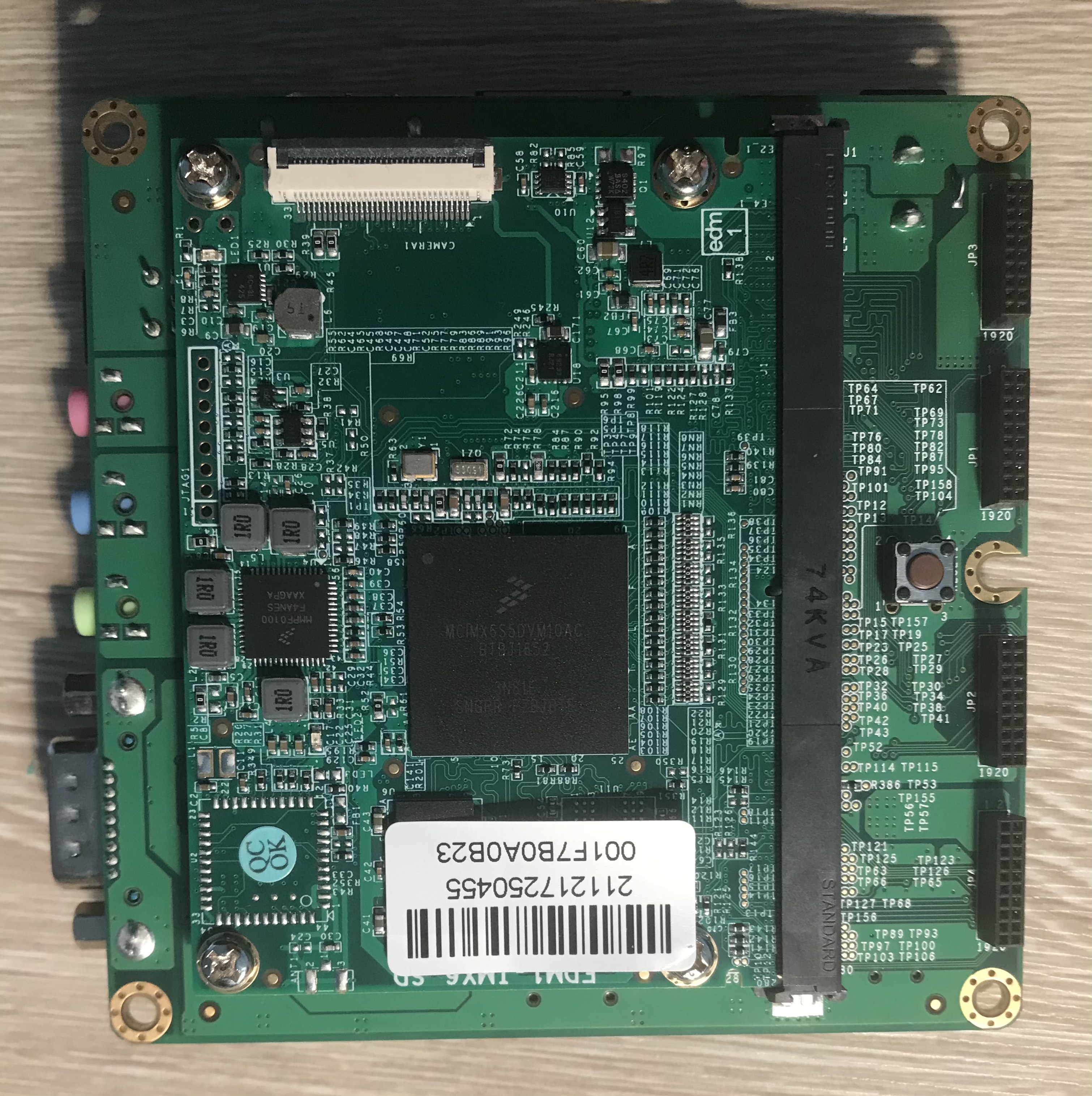
                When attempting to understand an unknown device, say a router you bought from eBay, or a guitar pedal, or any number of other gadgets, a very useful first step is visual inspection. There is quite a lot to PCB analysis and component identification, but that is outside of the scope of this article. What we are interested in here is the main processor, which should be fairly easy to spot -- It will likely be the largest component, be roughly square shaped, and have many of the traces on the PCB running to/from it. Some examples:


                More specifically, we're interested in the markings on the chip. Generally, these will include a brand insignia and model/part number, which can be used together to identify the chip.


                Much like Rumpelstiltskin, knowing the name of a processor grants you great power over it. Unlike Rumpelstiltskin, rather than magic, the source behind the power of the name of a processor is the ability to locate it's associated datasheets and reference manuals. Actually deriving a full processor name from chip markings can sometimes take some search-engine-fu, and further query gymnastics are often required to find the specific documentation you want, but generally it will be available. Reverse engineering completely undocumented custom processors is possible, but won't be covered in this article.

                Pictured below are the chip markings for our target device, with the contrast cranked up for visibility.


                We see the following in this image:

                • Analog Devices logo, as well as a full company name
                • A likely part number, "ADSP-BF547M"
                • Several more lines of unknown meaning
                • A logo containing the word "Blackfin"

                From this, we can surmise that this chip is produced by Analog Devices, has part number ADSP-BF547M, and is associated with something called Blackfin. With this part number, it is fairly easy to acquire a reference manual for this family of processors: the Analog Devices ADSP-BF54x. With access to the reference manual, we now have everything we need to understand this architecture, albeit in raw form. We can see from the manual that the Blackfin marking on the chip is in fact referring to a processor family, which all share an ISA, which itself is known also known as Blackfin. The the Blackfin Processor Programming Reference includes the instruction set, with a description of each operation the processor is capable of, and the associated machine code.

                So that's it, just dump the firmware of the device and hand-translate the machine code into assembly by referencing instructions in the manual one by one. Easy!

                Just Kidding

                Of course, translating machine code by hand is not a tenable strategy for making sense of a piece of software in any reasonable amount of time. In many cases, there are existing tools and software which can allow for the automation of this process, broadly referred to as "disassembly." This is part of the function served by tools such as IDA and Binary Ninja, as well as the primary purpose of less complex utilities, such as the Unix command line tools "objdump." However, as every ISA will encode machine instructions differently (by definition), someone, at some point, must do the initial work of automating translation between machine code and assembly the hard way for each ISA.

                For popular architectures such as x86 and ARM, this work has already been done for us. These architectures are well supported by tools such as IDA and Binary Ninja by default, as well as the common executable file formats for these architectures, for example the Executable and Linkable Format (ELF) on linux and Portable Executable (PE) on Windows. In many cases, these architectures and formats will be plug-and-play, and you can begin reverse engineering your subject executable or firmware without any additional preperation or understanding of the underlying mechanisms.

                But what do you do if your architecture and/or file format isn't common, and is not supported out of the box by existing tools? This was a question I had to answer when working with the Blackfin processor referenced earlier. Not only was the architecture unfamiliar and uncommon, but the file format used by the operating system running on the processor was a fairly obscure one, binary FLAT (bFLT), sometimes used for embedded Linux systems without a Memory Management Unit (MMU). Additionally, as it turned out and will be discussed later, the version of bFLT used on Blackfin-based devices didn't even conform to what little information is available on the format.

                Working Smarter

                The best option, when presented with an architecture not officially supported by existing tooling, is to use unofficial support. In some cases, some other poor soul may have been faced with the same challenge we are, and has done the work for us in the form a of a plugin. All major reverse engineering tools support some kind of plugin system, with which users of said software can develop and optionally share extra tooling or support for these tools, including support for additional architectures. In the case of Binary Ninja, the primary focus for this article, "Architecture" plugins provide this kind of functionality. However there is no guarantee that a plugin targeting your particular architecture will either exist, or work the way you expect. Such is open source development.

                If such a convenient solution does not exist, the next step short of manually working from the reference manual requires getting our hands dirty and cannibalizing existing code. Enter the venerable libopcodes. This library, dating back at least to 1993, is the backbone that allows utilities such as objdump to function as they do. It boasts an impressive variety of supported architectures, including our target Blackfin. It is also almost entirely undocumented, and its design poses a number of issues for more extensive binary analysis, which will be covered later.

                Using libopcodes directly from a custom disassembler written in C, we can begin to get some meaningful disassembly out of our example executable.


                However, an issue should be immediately apparent: the output of this custom tool is simply text, and immutable text at that. No semantic analysis has or can take place, because of the way libopcodes was designed: it takes machine code supplied by the user, passes it through a black box, and returns a string which represents the assembly code that would have been written to produce the input. There is no structural information, no delineation of functions, no control flow information, nothing that could aid in analysis of binaries more complex than a simple "hello world." This introduces an important distinction in disassembler design: the difference between disassembly and decomposition of machine code.

                Disassembly

                The custom software written above using libocpdes, and objdump, are disassemblers. They take an input, and return assembly code. There is no requirement for any additional information about a given instruction; to be a disassembler, a piece of software must only produce the correct assembly text for a given machine instruction input.

                Decomposition

                In order to produce correct assembly code output, a disassembler must first parse a given machine instruction for meaning. That is, an input sequence of ones and zeros must be broken up into its constituent parts, and the meaning of those parts must be codified by some structure which the disassembler can then translate into a series of strings representing the final assembly code. This process is known as decomposition, and for those familiar with compiler design, is something like tokenization in the other direction. For deeper analysis of a given set of machine instructions (for example a full executable containing functions) decomposition is much more powerful than simple disassembly.

                Consider the following machine instruction for the Blackfin ISA:

                Hex: 0xE2001000; Binary: 1110 0010 0000 0000 0001 0000 0000 0000
                

                Searching the reference manual for instructions which match this pattern, we find the JUMP.L instruction, which includes all 32 bit values from 0xE2000000 to 0xE2FFFFFF. We also see in this entry what each bit represents:


                We see that the first 8 bits are constant - this is the opcode, a unique prefix which the processor interprets first to determine what to do with the rest of the bits in the instruction. Each instruction will have a unique opcode.

                The next 8 bits are marked as the "most significant bits of" something identified as "pcrel25m2," with the final 16 bits being "least significant bits of pcrel25m2 divided by 2." The reference manual includes an explanation of this term, which is essentially an encoding of an immediate value.

                Based on this, the machine instruction above can be broken up into two tokens: the opcode, and the immediate value. The immediate value, after decoding the above instruction's bits [23:0] as described by the manual, is 0x2000 (0 + (0x1000 * 2)). But how can the opcode be represented? It varies by architecture, but in many cases an opcode can be translated to an associated assembly mnemonic, which is the case here. The E2 opcode corresponds to the JUMP.L mnemonic, as described by the manual.

                So then our instruction, 0xE2001000 translates into the following set of tokens:

                Instruction {
                    TokenList [
                        Token {
                            class: mnemonic;
                            value: "JUMP.L";
                        },
                        Token {
                            class: immediate;
                            value: 0x2000;
                        }
                    ]
                }
                

                For a simple text disassembler, the processing of the instruction stops here, the assembly code JUMP.L 0x2000 can be output based on the tokenized instruction, and the disassembler can move on to the next instruction. However, for more useful analysis of the machine code, additional information can be added to our Instruction structure.

                The JUMP.L instruction is fairly simple; the reference manual tells us that it is an unconditional jump to a PC-relative address. Thus, we can add a member to our Instruction structure indicating this: an "Operation" field. You can think of this like instruction metadata; information not explicitly written in the associated assembly, but implied by the mnemonic or other constituent parts. In this case, we can call the operation OP_JMP.

                Instruction {
                    Operation: OP_JMP;
                    TokenList [
                        Token {
                            class: mnemonic;
                            value: "JUMP.L";
                        },
                        Token {
                            class: immediate;
                            value: 0x2000;
                        }
                    ]
                }
                

                By assigning each instruction an Operation, we can craft a token parser which does more than simply display text. Because we are now encoding meaning in our Instruction structure, we can interpret each component token based on its associated meaning for that instruction specifically. Taking JUMP.L as an example, it is now possible to perform basic control flow analysis: when the analysis tool we are building sees a JUMP.L 0x2000, it can now determine that execution will continue at address PC + 0x2000, and continue analysis there.

                Our Instruction structure can be refined further, encoding additional information specific to it's instruction class. For example, in addition to the unconditional PC-relative jump (JUMP.L), Blackfin also offers conditional relative jumps, and both absolute and relative jumps to values stored in registers.

                For conditionality and whether a jump is absolute or relative, we can add two more fields to our structure: a Condition field and a Relative field, as follows.

                Relative unconditional JUMP.L 0x2000:

                Instruction {
                    Operation: OP_JMP;
                    Condition: COND_NONE;
                    Relative: true;
                    TokenList [
                        Token {
                            class: mnemonic;
                            value: "JUMP.L";
                        },
                        Token {
                            class: immediate;
                            value: 0x2000;
                        }
                    ]
                }
                

                Absolute unconditional to register JUMP P5:

                Instruction {
                    Operation: OP_JMP;
                    Condition: COND_NONE;
                    Relative: false;
                    TokenList [
                        Token {
                            class: mnemonic;
                            value: "JUMP";
                        },
                        Token {
                            class: register;
                            value: REG_P5;
                        }
                    ]
                }
                

                Conditional jumps appear more complex represented in assembly, but can still be represented with the same structure. CC is a general purpose condition flag for the Blackfin architecture, and is used in conditional jumps. The standard pattern for conditional jumps in Blackfin code looks like this:

                CC = R0 < R1;
                IF CC JUMP 0xA0;
                ...
                

                Conditional relative IF CC JUMP 0xA0:

                Instruction {
                    Operation: OP_JMP;
                    Condition: COND_FLAGCC;
                    Relative: true;
                    TokenList [
                        Token {
                            class: mnemonic;
                            value: "JUMP";
                        },
                        Token {
                            class: immediate;
                            value: 0xA0;
                        }
                    ]
                }
                

                We do not need tokens for the IF and CC strings, because they are encoded in the Condition field.

                All instructions can be broken down this way. Our decomposer takes machine code as input, and parses each instruction according to the logic associated with its opcode, producing a structure with the appropriate Operation, tokens and any necessary metadata such as condition, relativity, or other special flags.

                Our initial categorization of instruction based on opcode looks like this:


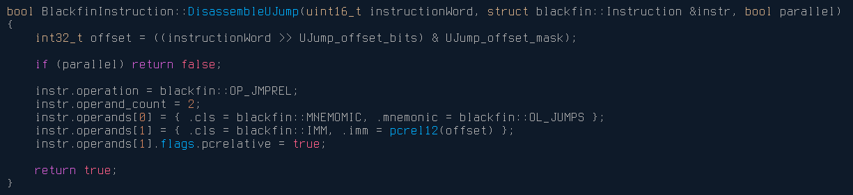
                And a simple example of decomposing the machine instruction (for the unconditional relative jump):


                For more complex instructions, the decomposition code can be much more involved, but will always produce an Instruction structure conforming to our definition above. For example, the PushPopMultiple instruction [--SP] = (R7:5, P5:1) uses a rather complicated encoding, and more processing is required, but still can be represented by the Instruction structure.


                The process of implementing decomposition logic can be somewhat tedious, given the number of instructions in the average ISA. Implementing the entirety of the Blackfin ISA took about a week and a half of effort, referencing both the Blackfin reference manual and the existing libopcodes implementation. The libopcodes opcode parsing logic was lifted nearly verbatim, but the actual decomposition of each instruction had to be implemented from scratch due to the text-only nature of the libopcodes design.

                Analysis

                Now we have our decomposer, which takes in machine instructions and outputs Instruction objects containing tokens and metadata for the input. I've said before "this information is useful for analysis," but what does this actually mean? One approach would be to write an analysis engine from scratch, but thankfully a powerful system already exists for this purpose: Binary Ninja and its plugin system. We'll be exploring increasingly more sophisticated analysis techniques using Binary Ninja, starting with recreating the basic disassembler we saw before (with the added perks of the Binary Ninja UI) and ending up with full pseudo-C decompiled code.

                We'll be creating a Binary Ninja Architecture Plugin to accomplish our goal here. The precise details for doing so are outside the scope of this article, but additional information can be found in this excellent blog post from Vector35.

                Basic Disassembly

                First, we'll recreate the text-only disassembler from earlier in the article, this time as a Binary Ninja plugin. This can be accomplished by defining a function called GetInstructionText in our plugin, which is responsible for translating raw machine code bytes to a series of tokens for Binary Ninja to display. Using our jump Instruction structure again, the process can be represented in pseudocode as follows:

                for token in Instruction.TokenList {
                    switch (token.class) {
                    case mnemonic:
                        BinaryNinjaOutput.push(InstructionTextToken, token.value);
                    case immediate:
                        BinaryNinjaOutput.push(IntegerToken, token.value);
                    etc...
                    }
                }
                

                This step completely ignores the operation and metadata we assigned each object earlier; only the tokens are processed to produce the corresponding instruction text, in other words, the assembly. After implementing this, as well as the necessary Binary Ninja plugin boilerplate, the following output is produced:


                Control Flow Analysis

                This looks a bit nicer than the text disassembler, but is essentially serving the same function. The code is interpreted as one giant, several hundred kilobyte function with no control flow information to delineate functions, branches, loops, and various other standard software constructs. We need to explicitly tell Binary Ninja this information, but thankfully we designed our decomposer in such a way that it already supplies this information inside the Instruction structure. We can single out any Operation which affects control flow (such as jumps, calls, and returns) and hint to Binary Ninja about how control flow will be affected based on the constituent tokens of those instructions. This process is implemented in the GetInstructionInfo function, and is as follows:


                With this implemented, the output is substantially improved:


                We now have individual functions, and control flow is tracked within and between them. We can follow branches and loops, see where functions are called and where they call to, and are much better equipped to actually begin to make sense of the software we are attempting to analyze.

                Now, we could stop here. This level of analysis combined with Binary Ninja's built-in interactivity is more than enough to make reasonable progress with your executable (assuming you know the assembly language of your target executable, which you certainly will after writing a disassembler for it). However, the next step we'll take is where Binary Ninja and its architecture plugins really shine.

                Lifting and Intermediate Languages

                At the time of its invention the concept of the assembler, which generates machine code based on human-readable symbolic text, was a huge improvement over manual entry of machine code by a programmer. It was made intuitive through the use of certain abstractions over manually selecting opcodes and allowed a programmer to use mnemonics and other constructs to more clearly dictate what the computer program should do. You could say that assembly is a higher level language than machine code, in that it abstracts away the more direct interactions with computer hardware in favor of ease of programming and program understanding.

                So how might we improve the output of our plugin further? While certainly preferable to reading raw machine code, assembly language isn't the easiest to follow way of representing code. The same kinds of abstractions that improved upon machine code can be applied again to assembly to produce a language at an even higher level, such as Fortran, C, and many others. It would be beneficial for our reverse engineering efforts to be able to read our code in a form similar to those languages.

                One way to accomplish this is to design a piece of software which translates assembly to the equivalent C-like code from scratch. This would require a full reimplementation for every new architecture and is the approach taken by the Hexrays decompilers associated with IDA -- the decompiler for each architecture is purchased and installed separately, and any architecture not explicitly implemented is entirely unsupported.

                Another approach is available, and it once again takes its cue from compiler design (which I will be oversimplifying here). The LLVM compiler architecture uses something called an Intermediate Representation (IR) as part of the compilation process: essentially, it is the job of the compiler frontend (clang for example) to translate the incoming C, C++, or Objective-C code into LLVM IR. The compiler backend (LLVM) then translates this IR into machine code for the target architecture. Credit to Robin Eklind for the following image from this blog covering LLVM IR:

                An important feature of this compiler architecture is its ability to unify many input languages into a single representational form (LLVM IR). This allows for modularity: an entire compiler need not be created for a new language and architecture pair, and instead only a frontend which translates that new language into LLVM IR must be implemented for full compilation capabilities for all architectures already supported by the LLVM backend.

                You may already see how this could be turned around to become useful processing machine code in the other direction. If some system can be designed which allows for the unification of a variety of input architectures into a single IR, the heavy lifting for translating that representation into something more conducive to reverse engineering can be left to that system, and only the "front-end" must be implemented.

                Allow me to introduce Binary Ninja's incredibly powerful Binary Ninja Intermediate Languages, or BNIL. From the Binary Ninja documentation on BNIL:

                The Binary Ninja Intermediate Language (BNIL) is a semantic representation of the assembly language instructions for a native architecture in Binary Ninja. BNIL is actually a family of intermediate languages that work together to provide functionality at different abstraction layers. BNIL is a tree-based, architecture-independent intermediate representation of machine code used throughout Binary Ninja. During each analysis step a number of optimizations and analysis passes occur, resulting in a higher and higher level of abstraction the further through the analysis binaries are processed.

                Essentially, BNIL is something akin to LLVM IR. The following flow chart is a rough representation of how BNIL is used within Binary Ninja:


                The portion of an Architecture plugin that produces the Lifted IL as described by that chart is known as the lifter. The lifter takes in the Instruction objects we defined and generated earlier as input, and based on the operation, metadata, and tokens of each instruction describes what operations are actually being performed by a given instruction to Binary Ninja. For example, let's examine the process of lifting the add instruction for the ARMv7 architecture.

                Assembly:

                add r0, r1, 0x1
                

                Instruction object resulting from decomposition:

                Instruction {
                    Operation: OP_ADD;
                    TokenList [
                        Token {              // Instruction mnemonic
                            class: mnemonic;
                            value: "add";
                        },
                        Token {              // Destination register
                            class: register;
                            value: REG_R0;
                        },
                        Token {              // Source register
                            class: register;
                            value: REG_R1;
                        },
                        Token {              // Second source (here immediate value)
                            class: immediate;
                            value: 0x1;
                        }
                    ]
                }
                

                Based on the assembly itself, the ARM reference manual, and our generated Instruction object, we understand that the operation taking place when this instruction is executed is:

                Add 1 to the value in register r1
                Store the resulting value in register r0
                

                Now we need some way of indicating this to Binary Ninja. Binary Ninja's API offers a robust collection of functions and types which allow for the generation of lifted IL, which we can use to this end.

                Relevant lifter pseudo-code (with simplified API calls):

                GetInstructionLowLevelIL(const uint8_t *data, uint64_t addr, size_t &len, LowLevelILFunction &il) {
                    Instruction instr = our_decompose_function(data, addr);
                    switch (instr.Operation) {
                    ...
                    case OP_ADD:
                        REG dst_reg = instr.TokenList[1];
                        REG src_reg = instr.TokenList[2];
                        int src2    = instr.TokenList[3];
                        il.AddInstruction(
                            il.SetRegister(
                                il.Register(dst_reg)
                                il.Add(
                                    il.Register(src_reg), 
                                    il.Const(src2)))
                        );
                    ...
                    }
                }

                The resulting API call reads "set the register dst_reg to the expression 'register src_reg plus the constant value src2'", which matches the description in plain english above.

                If after completing the disassembly portion of your architecture plugin you found yourself missing the abject tedium of writing an unending string of instruction decomposition implementations, fear not! The next step in creating our complete architecture plugin is implementing lifting logic for each distinct Operation that our decomposer is capable of assigning to an instruction. This is not quite as strenuous as the decomposition implementation, since many instructions are likely to have been condensed into a single Operation (for example, Blackfin features 10 or so instructions for moving values into registers; these are all assigned the OP_MV Operation, and a single block of lifter logic covers all of them).

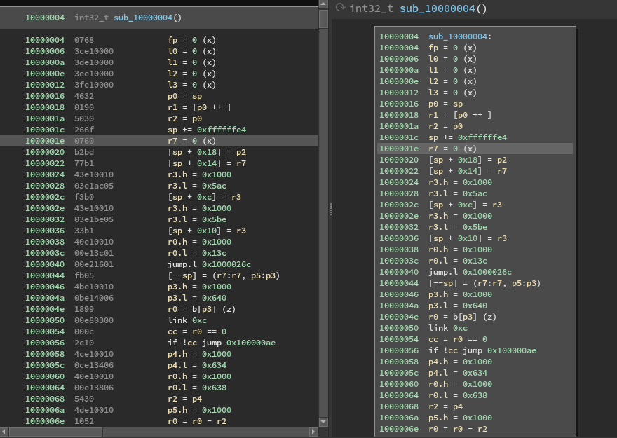
                Once the lifter has been implemented, the full power of Binary Ninja is available to us. In the Binary Ninja UI, we can see the lifted IL (on the right) our plugin now generates alongside the disassembly (on the left):


                You're forgiven for thinking that it is a bit underwhelming for all the work we've put in to get here. However, take another look at the Binary Ninja analysis flow chart above. Now that our plugin is generating lifted IL, Binary NInja can analyze it to produce the higher-level IL representations. For reference, we'll be looking at the analysis of a Blackfin executable compiled from the following code:

                int
                add4(int x, int y, int z, int j)
                {
                    return x + y + z + j;
                }
                
                int
                main()
                {
                    int x, y, z, j;
                    x = 1;
                    y = 2;
                    z = 3;
                    j = 0x12345678;
                    return add4(x, y, z, j);
                }

                Finally, let's take a look at the high-level IL output in the Binary Ninja UI (right), alongside the disassembly:


                As you might guess, reverse engineering the code on the right can be done in a fraction of the time it would take to reverse engineer pure assembly code. This is especially true for an obscure architecture that might require frequent trips to the manual (what does the link instruction do again? Does call push the return address on the stack or into a register?). Furthermore this isn't taking into account all of the extremely useful features available within Binary Ninja once the full analysis engine is running, which increase efficiency substantially.

                So, there you have it. From zero knowledge of a given architecture to easily analyzable pseudo-C in about two weeks, using just some elbow grease and Binary Ninja's excellent BNIL.

                ...

                Keen readers may have noticed I carefully avoided discussing a few important details -- while we do now have the capabilities to produce pseudo-C from raw machine code for the Blackfin architecture, we can't just toss an arbitrary executable in and expect complete analysis. A few questions that still need to be answered:

                1. What is the function calling convention for this platform?
                2. Are there syscalls for this platform? How are they handled?
                3. What is the executable file format? How are the segments loaded into memory? Are they compressed?
                4. Where does execution start?
                5. Is dynamic linking taking place? If so, how should linkage be resolved?
                6. Are there relocations? How are they handled?

                Since this article is already a mile long, I'll save exploration and eventual answering of these questions for an upcoming Part 2. As a preview though, here's some fun information: Exactly none of those questions have officially documented answers, and the unofficial documentation for the various pieces involved, if it existed in the first place, was often outright incorrect. Don't put away that elbow grease just yet!

                References